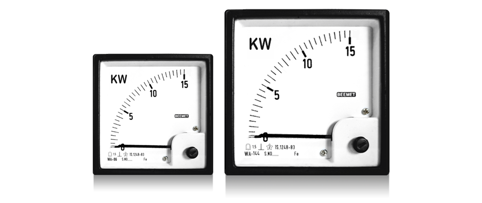
WA - 144
WA - 96
Beemet Watt meters are available in Single Phase, 3-Phase balanced load 3 or 4 wire, and 3-phase unbalanced load 3 or 4 wire configurations. They are used to indicate import – export (reverse – forward) power flow. These can be utilized on both sinusoidal and non-sinusoidal currents.
These meters are designed to an internationally accepted standard. The dimensions comply with the requirements of DIN 43700 and scales with DIN 43802. The performance confirms to IS 1248-83/93. The cases are made of ABS plastic material which has high tracking index for maximum electrical strength and safety.
Salient Features
• In-built electronic power converter.
• Rugged movement ensures sustained accuracy and reliability.
• Square bezel permits edge to edge mounting, allowing maximum use of panel space.
• Interchangeable dial for range portability.
• Clear scaling for easy reading.
• Specially customised dials.
• Flame retardant case available as per request.
General Specifications
| Accuracy | ±1.5 / 2.0 of FSD |
| Measurable Quantities | Active and Reactive Power |
| Pointer deflection | 0 - 90º |
| Input | Full-scale power value Pw or Pb |
| Feasibility factor | "Lambda"=Pw/Ps or Pb / Ps |
| Power factor | Cosφ = 1 ± 0.01 for Watt meters & Sinφ = 1 ± 0.01 for Var meters |
| Voltage | Rated voltage + 2% |
| Frequency | 45-65 Hz (50 Hz ±0.1% for E1B) |
| Current | 20% to 120% of rated current |
| Overload Capacity | According to IS: 1248 / IEC 51 |
| Short duration | 2 times rated voltage for 5s: 1 overload 10 times rated current for 5s: 1 overload |
| Continiously | 1.2 times rated voltage or current |
| Operating Temperature | -10 to 55°C |
| Storage Temperature | -25 to 65°C |
| Relative Humidity | < 75% annaul average, non-condensing |
Range Chart
| Model | Description | Current( Amp ) | Voltage( volt ) |
|---|---|---|---|
| WA-96, 144 | 1 Phase 1 Element | 1, 5, 10 | 63.5, 230 |
| WA-96, 144 | 3 Phase 1 Element Balanced Load only |
1, 5, 10 | 110, 440 |
| WA-96, 144 | 3 Phase 2 Element [3 Wire] Balanced or Unbalanced Load |
1, 5 | 110, 440 |
| WA-96, 144 | 3 Phase 3 Element [4 Wire] Balanced or Unbalanced Load |
1, 5 | 110/ 3, 440/3 |
Dimensions

| Model | Dimensions (mm) | Scale Length | |||||
|---|---|---|---|---|---|---|---|
| A | B | C | D | E | Panel Cutout | ||
| WA- 96 | 96 | 90 | 106 | 91.5 | 5.5 | 92x92 | 97 |
| WA -144 | 144 | 136 | 106 | 137.5 | 5.5 | 138x138 | 146 |
Connections
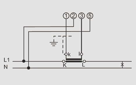
E1W-Single phase(one element)
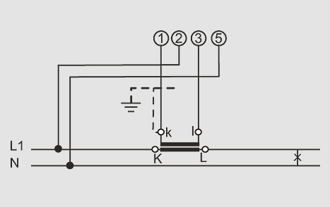
E1B-Single phase(one element)
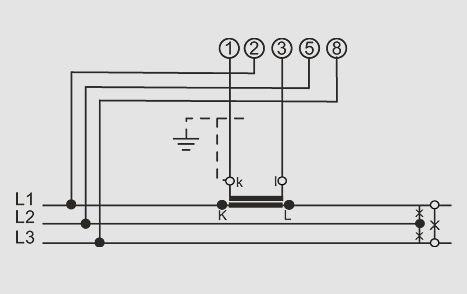
D1W -Three phase, three-wire
AC Supply with balanced load(one element)
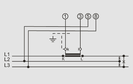
D1B -Three phase, three-wire
AC Supply with balanced load(one element)
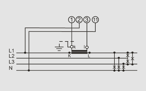
V1W -Three phase, four-wire
AC Supply with balanced load(one element)
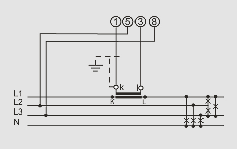
V1B -Three phase, four-wire
AC Supply with balanced load(one element)
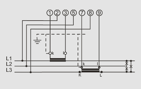
D2W -Three phase, three-wire
AC Supply with unbalanced load(two element)
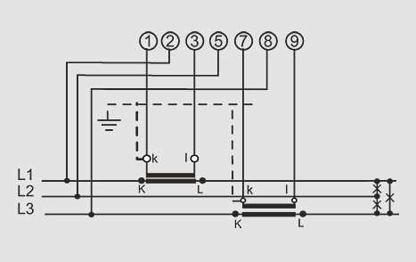
D2B -Three phase, three-wire
AC Supply with unbalanced load(two element)
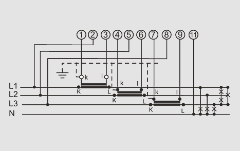
V3W -Three phase, four-wire
AC Supply with unbalanced load(three element)
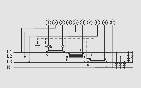
V3B -Three phase, four-wire AC
Supply with unbalanced load(three element)
FAQ
A wattmeter is an instrument used for measuring electrical power in a circuit. It measures the amount of power consumed in watts. Containing two coils where the current coil carries the load current and the potential coil measures the voltage across the load. This device is essential for monitoring energy usage and ensuring efficient operation in electrical systems. Learn more.
A wattmeter is used to measure the electrical power consumed or generated in a circuit, providing important data about energy usage, helping to monitor efficiency and identify potential savings. It also optimizes power consumption and ensures systems operate effectively.
A wattmeter is designed to provide accurate readings regardless of the current type thus being able to measure both AC and DC power. Additional components are included to account for phase differences between voltage and current in AC circuits, while the measurements are straightforward in the DC circuits. This difference makes wattmeters essential tools in various electrical applications.
A wattmeter typically has four terminals. Two terminals are used for measuring voltage, while the other two are for measuring current, thus allowing the wattmeter to accurately calculate electrical power in a circuit.
A wattmeter works by measuring the electrical power in a circuit through two main components: a current coil and a potential coil. These coils set in different patterns create a magnetic field based on a voltage. The interaction of these magnetic fields creates a force that moves a pointer on the wattmeter’s scale, indicating the power consumption in watts.
- Identify the voltage and current terminals on the wattmeter.
- Turn on the wattmeter.
- Set the appropriate measurement parameters.
- If using an analog wattmeter, the pointer position on the scale is noted.
- For digital models, the numerical value is read from the screen.
- After taking multiple readings for accuracy, turn off the wattmeter.
Wattmeter has multiple applications:
- To measure electrical power in circuits.
- Monitoring energy consumption and efficiency in
- Residential
- Commercial
- Industrial settings.
- To assess the power usage of appliances
- Used in laboratories for specific testing purposes.
- Used in industries to check power ratings and consumption of electrical devices
- An AC wattmeter is designed to measure alternating current, which changes direction periodically, while a DC wattmeter measures direct current, which flows in one direction.
- AC wattmeters often include additional components to measure for the phase difference between voltage and current, while in DC wattmeters typically use simpler mechanisms since the current flow is constant.
