Salient Features
• All ratios available to match commonly available ELRs.
• Compact.
• Light weight.
• Encapsulated ABS moulding.
• Terminals are finger proof touch as per IEC 44-1 and IEC185
• Cost effective.
Advantages
• Highly linear.
• Highly accurate.
• Light in weight.
Applications
• For detection of leakage current & transmiting proportional signal to ELR.
Supply Specifications
| Supply Voltage | 90-270V AC/DC (±15%) |
| Supply Frequency | 50/60 Hz |
| Power Consumption | 3VA max. |
Output SPECIFICATIONS
| Alarm Relay Output( optional ) | 50% of Range 1 SPDT switch NO(5A and 240V AC) NC (5A and 240V AC) |
| Trip Relay Output | 80-90% of Range 1 SPDT switch NO (5A and 240V AC) NC (5A and 240V AC) |
| Relay Contacts | 1 potential free contact (NO,C & NC) |
| Contact Rating | 6A/230V AC/28V D |
Technical Specifications
| System Voltage | 720V max. |
| Insulation Voltage | 3 kV for 1 minute |
| System Frequency | 50/60 Hz |
| Maximum permissible current | 1 kA continuous 5 kA for 1.5 sec |
| Current Ratio | 1/1000, 1/600 any other on request |
Mechanical Specifications
| Terminal conductor | ≤ 2.5 sq.mm |
| Distance between toroid and relay | < 50 meters |
| Enclosure | Flame retardant glass filled ABS |
| Mounting | Four fixing slots |
Environmental SPECIFICATIONS
| Operating Temperature | -20°C to 70°C |
| Humidity | <95 RH |
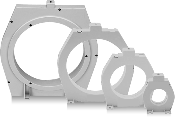
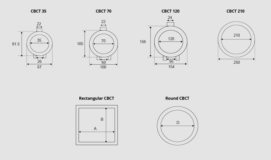
DImensions
Inner Diameter : 35mm Weight : 80
Inner Diameter : 70mm Weight : 125 g
Inner Diameter : A x B
Inner Diameter : D
Inner Diameter : 120mm Weight : 190 g
Inner Diameter : 210mm Weight : 250 g
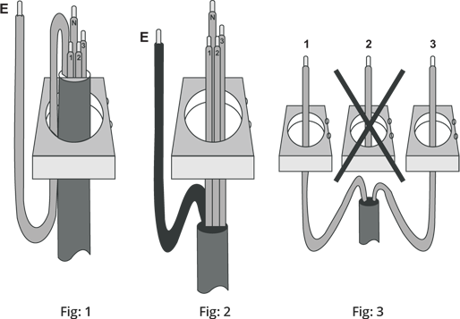
Installation Guidelines
Correct installation of the Earth Lekage Relay and toroid should ensure trouble free operation, if this documents is followed.
• Always ensure the Earth conductor Does Not pass through the toroid. If it is unavoidable,
the Earth must be routed back through the toroid again and around, as shown in Fig:2 beside.
• As a rule, select a toroid that has an inside diameter which is twice that or greater than
the outsider diameter of the cables to be passed through.
• Ensure the cable is central in the toroid.
• Place the toroid on a straight, section of cable, not near a bend.
• Keep the cable and toroid from intense magnetic fields from nearby equipment.
• Do not pass individual through seperate toroids, as shown in Fig: 3
Connection Diagram

FAQ
The full form of CBCT in the electrical system is the Core Balance Current Transformer. It plays a crucial role in detecting earth faults and imbalances in 3-phase electrical systems, making it an essential component in maintaining electrical safety and efficiency. CBCT electrical systems are commonly used in various applications to monitor and prevent faults.
A CBCT connection diagram looks like a ring-type transformer through which 3 single-core cables or 1 three-core passes. This structure allows CBCT to measure the current without direct contact.
The working principle of CBCT relies on detecting zero sequence currents. It generates a signal that activates an earth fault relay to isolate the faulty circuit when there is an imbalance in a three-phase system.
The CBCT specification includes multiple things like high sensitivity to leakage currents, operating current ranges from 30mA to 30A and various inner diameters. These features make it suitable for different applications in electrical systems.
You can start CBCT installation by clamping the CBCT around the conductor without disconnecting the power supply. This ensures safety and ease during installation.
There are various advantages of CBCT, such as :
- High-Quality Imaging
- Reduced Radiation Exposure
- Comprehensive Views
- Non-Invasive Procedure
- Enhanced Patient Understanding