Is raw power alone enough to ensure the proper functioning of electrical control panels? The answer is NO. Panels require a stable power supply to function smoothly. Even minor voltage inconsistencies can trigger nuisance trips, compromise sensitive components, or shut systems down entirely.
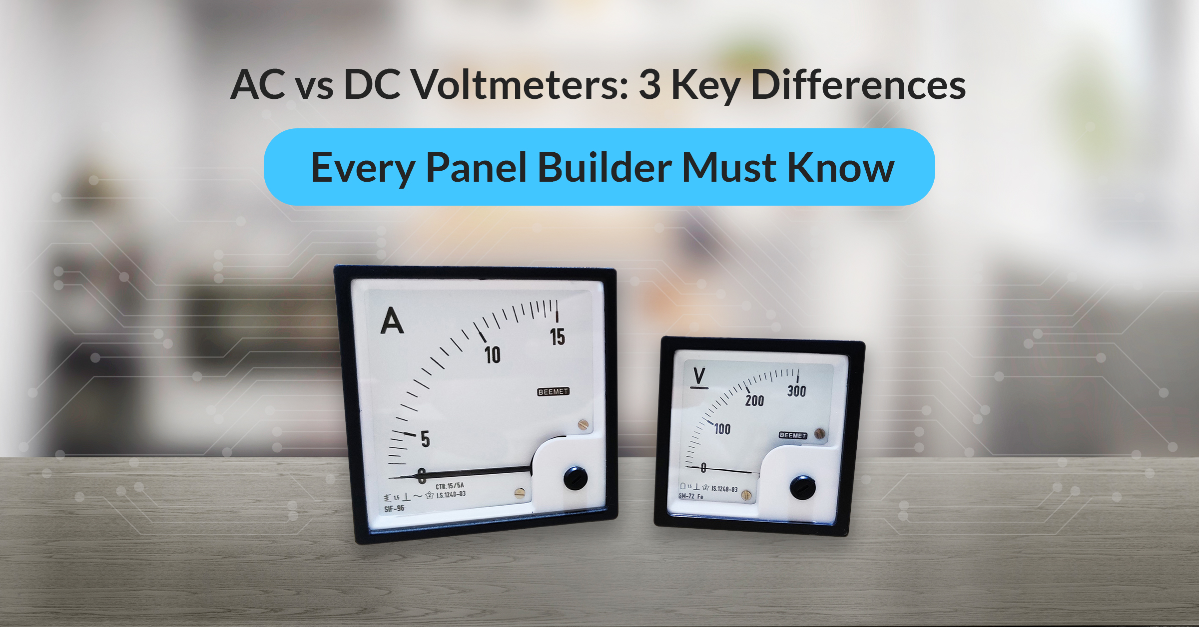
While breakers and relays seem like critical components in the design of control panels, there is a simple yet important element that can help – the voltmeter. This instrument confirms the stability of supply. The wrong type of voltmeter choice can create instability within the system.
Before selecting components, panel builders must clearly understand how voltage is measured. Especially how AC and DC systems demand fundamentally different measurement approaches.
Role of Voltmeters in Electrical Panels
A voltmeter is a device that checks if uninterrupted electrical power is real time. It shows drops and also alerts when an overload occurs, allowing professionals to check lapses without complete disruption.
In practical panel applications, voltmeters work alongside operators, relays, and breakers to eliminate guesswork around power conditions. Because they offer immediate visibility of fluctuations, they help teams detect irregularities before they escalate.
A voltmeter validates the system and is among the best electrical measuring instruments for checking power flow through the panel. Confirming that the supplied voltage remains within acceptable limits is a critical indicator of the panel’s operational reliability.
For a deeper understanding of voltmeter types and their working principles, refer to our complete guide to voltmeters.
AC vs. DC Voltmeters: Definitions and Panel Uses
- AC Voltmeter: It measures alternating voltage, where the current periodically reverses direction at a specific frequency. This is commonly found in grid supply lines and distribution systems.
- DC Voltmeter: It monitors direct current with a constant, unidirectional flow. This is often utilized in batteries, solar systems, and DC control sections.
AC and DC both perform in unique ways. AC meters evaluate a fluctuating waveform before displaying useful data, while DC meters directly read stable power. This distinction is immediately apparent when inspecting the interior of a panel.
AC vs. DC Voltmeters: 3 Critical Differences for Panel Builders
1. Type of Voltage Measured
One of the three critical differences is the type of voltage measured. DC voltage remains constant but AC voltage may fluctuate in magnitude and direction. AC meters calculate an effective value to display the power provided, whereas DC meters give voltage values.
When there are differences between the voltmeter types, the voltmeters’ accuracy can suffer. Using an improper voltage meter might provide unstable results. Usually, the problem only becomes evident during live testing, when the readings fail to reflect actual conditions.
2. Application Inside Electrical Panels
The next difference is the application inside electrical panels. DC meters use control sections, battery banks, and UPS systems to monitor stable voltage sources. Generally, the supply paths, transformer outputs, and distribution portions utilise AC meters.
Modern electrical panels use different types of voltmeters. These are often digital voltmeters, including multifunction gadgets. It is important that the configuration matches the waveform we intend to measure.
3. Impact on Panel Instrumentation and Safety
The third difference lies in the impact on panel instrumentation and safety.
DC and AC meters operate on different principles. Most DC meters use a moving coil mechanism that directly moves the pointer. AC meters, however, employ moving iron or electric principles. They use rectifiers and filtering to handle switching signals more effectively.
With additional processing stages, AC meters may be less accurate, particularly with distorted waveforms. These changes are significant because they affect panel instrumentation stability and compliance.
Quick Comparison
The table below shows a quick comparison between the two:
|
Aspect |
AC Meter |
DC Meter |
|
Current Type |
Alternating |
Direct |
|
Mechanism |
Electromagnetic / processed |
Moving coil |
|
Reading |
Effective value |
Direct value |
|
Panel Use |
Supply sections |
Control and battery circuits |
Voltmeter Types for Industrial Panels
Panel builders choose between conventional and digital meters depending on their application and environment. Moving coils make analog DC meters simple to use and dependable. AC analog meters display signal changes with electromagnetic response.
However, digital meters are becoming increasingly popular due to their clearer figures and reliability. This makes them common in electrical control panels. This adjustment is crucial in many industrial electrical panels where safety and efficiency must be monitored.
How Voltmeters Work in Panel Monitoring Systems
The basic voltmeter working principle is to measure the voltage differential between two points.
In devices powered by direct current (DC), it works by allowing a steady flow of current through its internal coil, which produces a straight output. When measuring AC circuits, the voltmeter converts the waveform to a steady reading.
When integrating voltmeters into PLC systems, this information on how voltmeters work is crucial. This is because many newer panels need to monitor continuous voltage to collect data and issue alerts.
Choosing the Right Voltmeter for Electrical Panel Design
- Builders must always look for the following while choosing a voltmeter:
- Begin by verifying the voltage range and the current type.
- Verify the accuracy class and confirm compatibility with other control panel components.
- System requirements must be met by isolation and appropriate rating.
- The meter should be tested under actual load conditions during electrical panel design, as catalog specifications alone do not reflect its true behavior.
- Proper selection helps prevent further problems.
Common Voltmeter Selection Mistakes in Panels
Some common selection mistakes include:
- Misreadings occur when measuring AC and DC with one meter.
- Ignoring waveform distortion may lead to inaccurate AC readings.
- Isolation neglect may cause grounding troubles.
- Inadequate candidate assessment during the selection process may lead to instability in system use.
Conclusion
Choosing the right voltmeter is essential for ensuring system accuracy and long-term panel reliability.
At Beemet, we know how critical these key details are. That’s why our voltmeters are designed to deliver consistent and precise readings in real-world industrial environments.
If you’re evaluating instrumentation options, our guide on how to select the right ammeter and voltmeter provides practical selection insights.
If you value precision and safety, explore Beemet’s range of reliable and sturdy voltmeters designed for dependable and accurate performance.
FAQ
AC voltmeters connected to DC sources may provide inaccurate readings. As it handles alternating signals, the output may be unstable or inaccurate.
The configuration must match the waveform for certain digital meters to measure both. Without proper setup and processing, voltage readings may be inaccurate.
Waveform distortion may affect the processing of AC meter signals. If filtering is inadequate, the reported figure may not represent power delivered.