Electrical measuring instruments are essential tools for monitoring, measuring, and analyzing electrical circuits and systems. These instruments play a crucial role in maintaining the safety, accuracy, and efficiency of electrical systems in various industries like construction, manufacturing, and electrical engineering.
This blog will help you to understand the different electrical measuring instruments, their applications and how to use these instruments correctly to get accurate readings.
What is an Electrical Circuit?
Electricity is a huge part of our lives now, without which it becomes impossible to access lights and fans, charge our many devices or even cook on our induction stoves. Come to see it, we have come a long way with electricity, but how well do we know it? We will start with the basics of an electrical circuit – the most integral part of electricity.
An electrical circuit is a closed loop for transmitting an electric current via electrical or magnetic fields. The electric current is made up of the flow of electrons across the path. Let us look at the fundamentals of an electric circuit to understand it better:
These electrons enter the circuit through the “source” which could either be a generator or a battery. The source sets up an electrical field, generating the electromotive force which provides energy to the electrons.
Electrons then leave the circuit through the load or output, reaching the earth’s ground, thus completing a closed path. A load may be a simple home appliance like a refrigerator, television, or lamp or a heavier load, such as one on a hydroelectric power generating station.
A simpler example of an electric circuit would consist of a source like a battery, which provides the necessary energy for the flow of electrons, and a conducting medium such as a wire, with the light bulb being the output/load.
Fundamentals of Electric Circuit
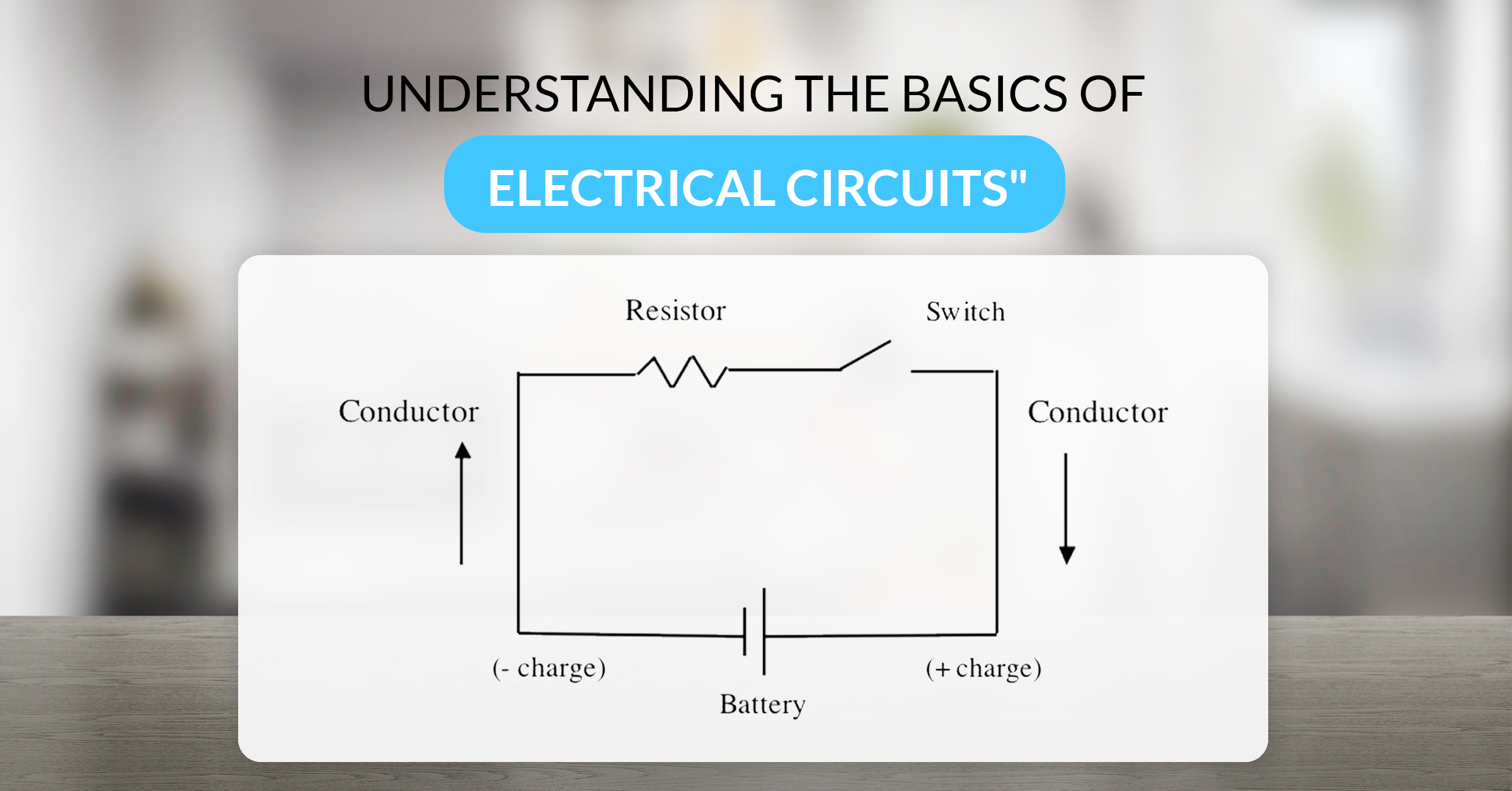
To put it very simply, three important parts make up an electric circuit. They are:
- A “source” or “power source” such as a battery, provides electric current throughout the circuit.
- A “conductor” such as a cable carries the current around the circuit.
- A “load” such as any normal home appliance like a refrigerator or something simpler like a bulb that holds resistance and changes the electric energy into different forms like light, heat or kinetic, etc.
The conductor connects the positive side of the source to the load, which is further connected to the negative side of the source, and the circuit is complete. Consequently, a current flows through the load, which converts the stored energy of the battery to another form.
However, a circuit might include other components like switches, diodes, resistors, fuses, relays, capacitors, etc., these three parts are fundamental to every electric circuit and thus are always present.
Basic Circuit Elements
A circuit is a nexus of many elements working together. Based on their capability to generate energy, these elements are classified into the following two types:
a. Active Circuit Elements
Elements that generate energy are called active elements in a circuit. Source elements are usually the most important active elements and their examples include generators, batteries, diodes and operational simplifiers.
An energy source, be it a current source or voltage, is of two types: Independent and Dependent sources. An independent source could be represented by a battery which provides consistent voltage to the circuit, irrespective of the current flowing through the terminals. A dependent source, on the other hand, could be represented by a transistor, which provides current to the circuit depending on the voltage applied to it. An operational amplifier too, provides voltage based on the differential input voltage applied to its terminals.
b. Passive Circuit Elements
Elements that control the flow of electrons through them are called passive elements in a circuit. The voltage is either increased or decreased by these elements, following are a few examples of the same:
Resistor: A resistor is an element that opposes the flow of current through it. Ohm’s law is applicable for a linear circuit, which states that the voltage across the resistor is directly proportional to the current flowing through it, the proportional constant being the resistance.
Inductor: An inductor is an element that stores energy in the form of the electromagnetic field. The voltage in and around an inductor is proportional to the rate of change of current flowing through it.
Capacitor: A capacitor is an element that stores energy in the form of the electrostatic field. The voltage through a capacitor is proportional to the charge.
Types of Electric Circuits

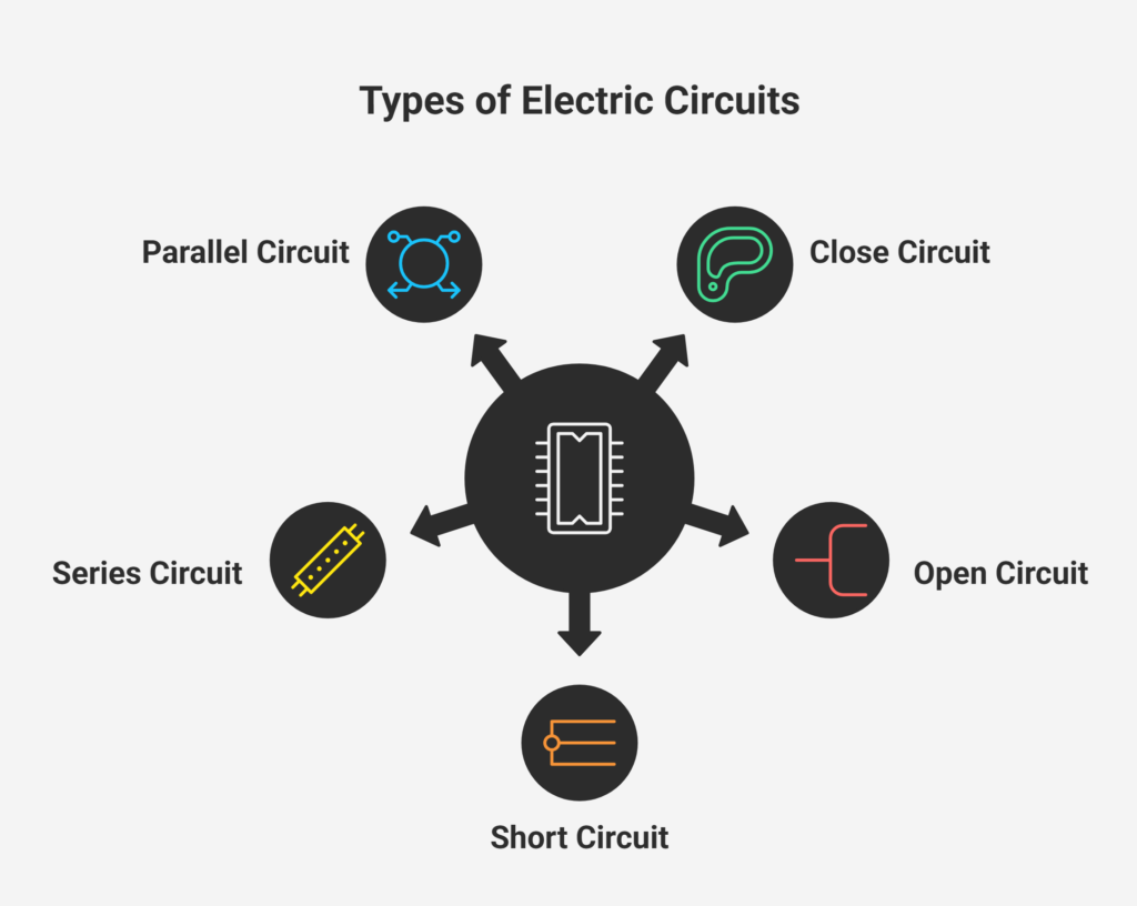
An electric circuit equips the conductive path for the flow of electric current or electric charge, and can be of the following five types:
Close Circuit
In a close circuit, the load and the source are connected and the source provides current to the load. Depending on the voltage magnitude of the source, the current flows through the circuit.
Open Circuit
The circuit becomes an open circuit when it is switched off or when the fuse is blown off due to some issues in the circuit. Under such conditions, the current flowing through the closed circuit is interrupted, followed by a disconnect between the source and the load.
Short Circuit
An insulation failure of the connecting wires or in the electrical equipment could result in a short circuit. In such a case of a short circuit, the connecting wires between the source and the load are affected by the short circuit. The current flow through the circuit is at its peak. It blows off the fuse, and the circuit then becomes an open circuit.
Series Circuit
When two or more pieces of electrical equipment are connected in a series, it becomes a series circuit. The magnitude of the current flowing through a series circuit in the equipment is the same. The current flows through a single path only. Series connection is also called end-to-end or cascade connection. Even if one piece of equipment is defective, the whole circuit then becomes an open circuit. There are some properties of series circuits to keep in mind:
– The magnitude of the current is the same throughout the load.
– The source voltage is equivalent to the sum of voltage drop through each load: V = V1 + V 2 + V3 … Vn.
Voltage can be easily measured using Beemet’s Voltmeters which give quick and accurate results.
– The equivalent resistance of the circuit is equivalent to the sum of individual load resistance: Req = V=R1 + R 2 + R3 … Rn
– The equivalent resistance is the highest out of all the individual resistances.Parallel Circuit
Two or more loads are connected across the supply source in a parallel circuit. According to Ohm’s Law, the lower resistance draws more current, and the higher resistance draws less current. Similarly, the current flowing through each load is dependent on the load resistance. The voltage, however, is the same across all the loads. The other load keeps operating even if one load disconnects. There are several properties that make up the parallel circuit which are as follows:
– The potential difference across all the parallel loads is the same.
– The distribution of the loads is carried out according to the individual load resistance,
– The total current derived from all the loads is equivalent to the sum of the individual currents of the loads:
l = l1+ l2 + l3 … ln
– The reciprocal of the equivalent resistance of a parallel circuit is equal to the sum of the reciprocal of individual resistances:
1/R = 1/R.1 + 1/R2 + 1/R3 … 1/Rn
– The equivalent resistance is lesser than even the smallest of all resistances linked in parallel:
R < R1, R < R2, … R < Rn
– Finally, the equivalent conductance is equal to the sum of individual conductances:
G = G1 + G2 + G3 … Gn
Basic Electric Circuit Components
Any basic electric circuit is made up of four essential components:
- A power source which could be alternating current (AC) or direct current (DC). Electricity at home is an AC power source, and a battery is a DC power source.
- A load transforms the electric energy to another form. An electric load such as a bulb converts electric energy to heat and light energies. Inductors, capacitors and resistors are all examples of an electric load.
- A switch that closes and opens the electric circuit. Once the switch is closed, the electric current flowing in the circuit provides electric energy to its components.
- Electric conductors (wires) with small or negligible internal resistance. Conductors connect the load to the power source with the help of a switch.
Application of Electric Circuits
As we initially discussed, electric circuits are all around us. Mobile phones, torches, and home appliances like television, AC, and microwave all have an intricate electric circuit working in the back. These are simple appliances we use in our day-to-day lives. Additionally, electric circuits are majorly present in industrial settings as well. Meters, resistors, semiconductors, counters, analyzers, and sensors to name a few.
Electric circuits can be harmful in nature, and must always be used with precautions. With the help of safe and precise products such as those from Beemet, you can regularly check on your equipment to avoid any mishaps in the future. Stay safe!
Read our complete guide on electrical measuring instruments here.
FAQ
An electrical circuit is a complete path that allows electric current to flow. It consists of a power source, a conductor, and a load, which converts electrical energy into another form of energy.
The basic components of an electric circuit includes:
- Power source
- Conductor
- Load
- Switch
A complete circuit works when the power source sends electrons through the conductor to the load. The load uses this energy and returns the current to the power source, forming a closed loop.
In a series circuit, components are connected end-to-end, and current flows through one path. In a parallel circuit, components are connected across the same voltage source, and the current splits across multiple paths.
A short circuit happens when a low-resistance path bypasses the load. This causes excessive current flow, which can damage the circuit and create safety hazards.
An open circuit occurs when there is a break in the loop, preventing current flow. This can happen due to a blown fuse, a broken wire, or an open switch.
- Active elements supply energy to the circuit.
- Passive elements control or store energy within the circuit.
Regular checks help detect faults like short circuits or damaged components. Using safe and accurate measuring instruments, ensures the circuit operates safely and efficiently.


