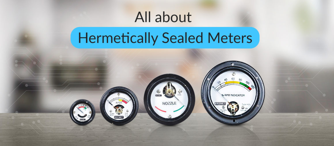
What are hermetically sealed meters? A meter with hermetic sealing blocks entry of moisture, dust and gas from the environment. These measuring instruments achieve precise results in all environmental conditions…
Blog
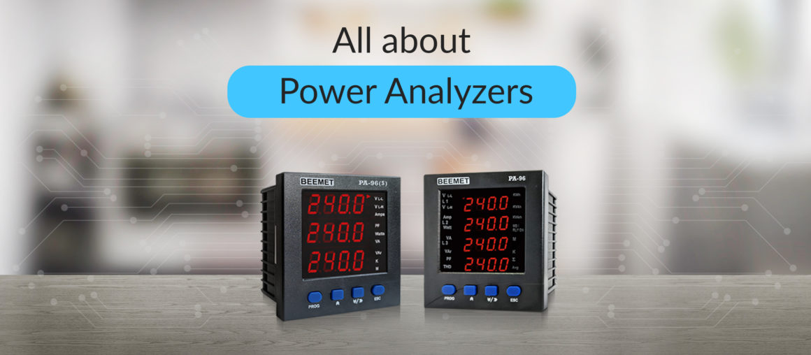
All About Power Analyzers
In this blog, we will dive deep into the world of power analyzers. We will cover topics like what they are, their different types, how they work, and their numerous…
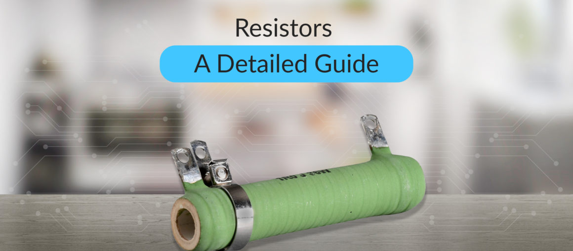
Resistor: A Detailed Guide
What are Resistors? A resistor is a simple two-terminal electrical component that opposes the flow of current. The flow of electrical current is restricted as the resistance value increases. This…
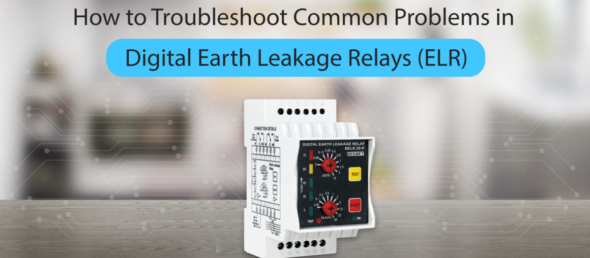
How to Troubleshoot Common Problems in Digital Earth Leakage Relays (ELR)
Modern electrical systems can cause safety and equipment hazards in case of earth leakage. Such dangers are usually prevented using digital Earth Leakage Relays (ELR). The moment it detects an…
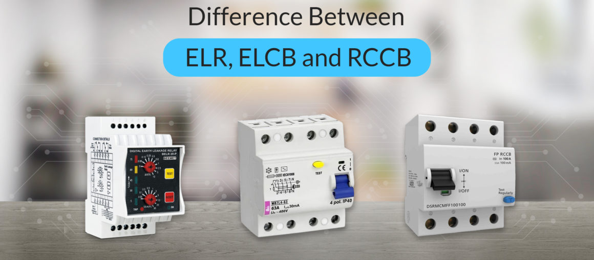
Difference Between ELR, ELCB and RCCB
Understanding the differences between ELR, ELCB, and RCCB is essential for ensuring electrical safety in residential, commercial, and industrial installations. Don’t let accidents be a rude wakeup call to be…
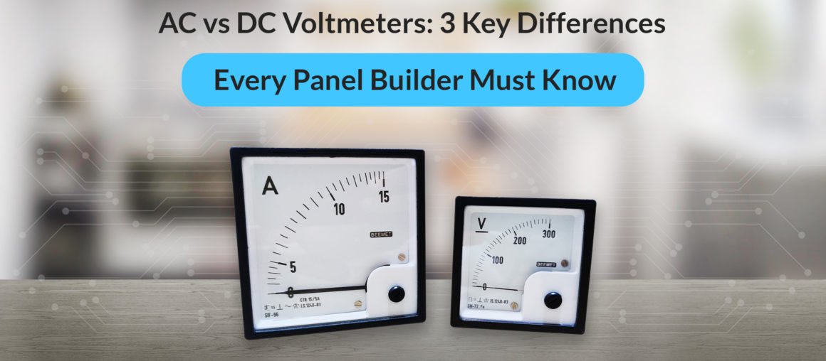
AC vs DC Voltmeters: 3 Key Differences Every Panel Builder Must Know
Is raw power alone enough to ensure the proper functioning of electrical control panels? The answer is NO. Panels require a stable power supply to function smoothly. Even minor voltage…