TL’DR: Current Transformers and Potential Transformers are essential components to measure high current and voltage in systems. CTs reduce current to safe levels for meters and relays, while PTs do the same for voltage. CTs function in series while the latter connect in parallel. Together, they ensure accurate monitoring, equipment safety, and support power system reliability. A vital component used by engineers, operators, and insurers alike.
Ever seen an entire building unit come to a grinding halt because of an unexpected electricity surge? Alarms go off, work stops, and equipment breaks down and there’s chaos all around. Before you know it, the damage is done. But here’s the real question: Were the protective systems in place doing their job?
Often tucked away in control panels and substations are instrument transformers, especially current transformers (CTs) and potential transformers (PTs). These play a silent yet critical role in preventing such disasters. It’s important to understand the role of instrument transformers. These components are more than just electrical gadgets, ensuring everything runs within safe limits.
This blog by Bemeet explains how these transformers help keep electrical equipment safe and running smoothly.
Why Instrument Transformers Matter
Direct measurement of high current and voltage has long been a challenging task in an electrical system. However, with the use of an instrument transformer, this task is very easy to beat. Potential transformer and current transformer are the two main forms of these instrument transformers. These devices lower voltage or current levels that are too high to levels that are safe for meters to read. As a result, systems are safe, readings are accurate, malfunctions are averted, and standards are met.
Basic Working Principle
Current and potential transformers measure with precision but never alter power. Let’s take a look at how they do it.
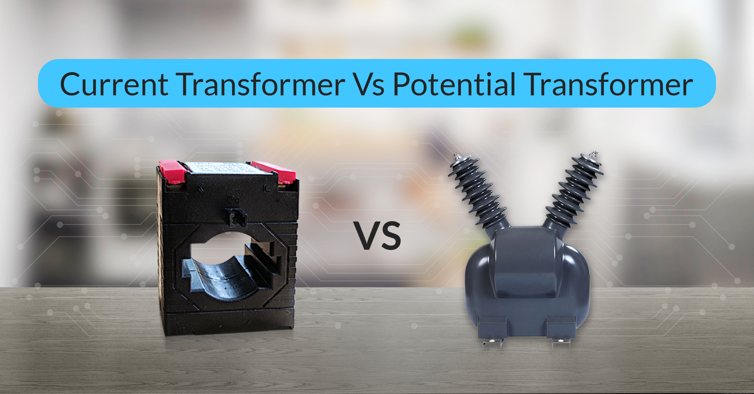
A current transformer (CT) reduces high current to safety levels, whilst a potential transformer (PT) does the same for voltage. Both use electromagnetic induction to transmit energy between coils.
The number of turns in the input and output wire coils (windings) influences how each transformer reduces voltage or current. The voltage in PTs is directly related to the number of turns. In CTs, current is inversely proportional.
In most cases, the secondary winding has more turns than the main winding. This makes it possible to safely and accurately lower the output. Current flows through the main winding when voltage is applied, generating electrical flux. This flow charges the secondary winding. The produced voltage reverses the current flow. The transformer maintains a stable magnetic field, allowing it to precisely scale down the input signal. This ensures connected devices are monitored safely and numbers are correct.
Note: It is dangerous to unplug a CT transformer while it is running. PTs also need to be properly grounded to keep themselves safe and avoid electrical problems.
Key Differences: CT vs PT
Now that you know what instrument transformers are and how they work, let’s explore the differences between them. Here’s a quick overview of the key distinctions in CT vs PT:
Feature | CT Transformer | PT Transformer |
Measurement Purpose | Lowers excessive current to instrument-safe levels. | Reduces high voltage to instrument level. |
Connection | Connected in series with the line being measured. | Connected in parallel with the line being measured. |
Primary & Secondary Windings | Primary: Few turns, carries line current. Secondary: Many turns, never open-circuited. | Primary: Many turns, carries line voltage. Secondary: Few turns can be open-circuited. |
Typical Output Range | Standard output current: 1A or 5A. | Standard output voltage: 100–120V (commonly 110V). |
They show how current and potential transformers guarantee safe operations and precise monitoring in power plants and substations.
Exploring the Use of CTs and PTS
Beyond simple measurement, CTs and PTs serve crucial functions. Here are some key real-world applications for various types of transformers.
CT Transformer Applications include:
- Energy metering (safely measuring high-current circuits)
- System protective relay control (scaling current to relays and devices)
- PT Transformer Applications include:
- Voltage measurement for metering purposes
- Protective relay and control device voltage supply (stepping down excessive voltages)
Want a deeper technical breakdown? Explore our definitive guide to Current Transformers to understand how they function and where they’re used across different industries.
Conclusion
All the way from power plants to the power grid, instrument transformers are important. Therefore, it is essential to know the differences between a CT and PT transformer to ensure accurate and safe power monitoring. Together, they make electrical systems work by lowering high numbers and finding faults, especially current transformers (CTs), a key product in our range at Beemet used for precise, high-load applications.
At Beemet, we simplify the complexities of power systems by empowering engineers, insurers, and decision makers with the insights they need to stay ahead. Follow us for expert backed guidance, practical tools, and real world solutions that keep your systems future ready.
For a broader look at how CTs, PTs, and other components fit into the bigger picture, take a look at our complete guide on electrical measuring instruments.
FAQS
When a CT’s secondary winding is opened under pressure, high voltage might damage the insulation or cause an electric shock. When not linked to instruments, CTs should be short-circuited.
Not at all. PT Transformers depend on electromagnetic induction, which can only work with AC. They don’t work and are dangerous for DC systems.
Accurate CT and PT readings show that the technology works even when the power goes out. They can use real-time load data to figure out what went wrong and make fair claims.